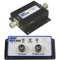

AMP24-500 Amplifier
AMP24-500
The RadioLinx AMP24-500 Amplifier series are Automatic Gain Control (AGC) compensated for constant power output bi-directional amplification. This provides constant maximum output power at the antenna over a wide RF input range. An antenna amplifier significantly improves the link reliability and operating range by low noise amplification in receive mode, and spectrally clean power amplification in transmit mode. This amplifier has unique internal filtering and AGC in both the Tx and Rx paths. This combination provides exceptional performance in high traffic areas.
The bi-directional amplifier may be needed if an application requires long lengths of coaxial cable to reach the antenna. The amplifier is designed to put maximum power right at the antenna and boost the received signal primarily to overcome cable loss and improve overall receiver signal quality. Only the AMP24-500 amplifier has been specifically FCC approved for use with RadioLinx radios.
Caractéristiques Avantages
- High dynamic range
- High Q filtering in both Tx and Rx paths
- Extremely low transmit harmonics
- Transmit AGC
- Low receive noise filter
- Internal lightning protection
- Rx high level AGC (Preserves noise figure while providing maximum input dynamic range even with high inband RF levels)
- Tx/Rx LED indicator
- Automatically switches between Rx/Tx
- Rugged weatherproof housing
Installation Guidelines
1 Each AMP24-500 amplifier is equipped with internal ¼ wave technology lightning protection
2 The AMP24-500 amplification device is a RadioLinx subassembly and its use has been FCC approved for use in an RF system. The AMP24-500 kit has been pre-designed to meet FCC approval and use under the following guidelines:
- The bi-directional amplifier has been designed to operate with a cable loss between the radio and amplifier of 6.5 dB to 20 dB. Within this range, the output of the amplifier will always be ½ W regardless of the input level
- The amplifier may not be used with less than 6.5 dB cable loss
- Use of the amplifier outside of these guidelines will result in violation of 47 CFR Part 15 FCC Rules, under which the equipment has been authorized
- With more than 20 dB of coaxial cable loss, the amplifier will not turn on
- Maximum antenna transmit gain allowed for use with the AMP24-500 amplifier is 15 dBi for point-to-point paths and 9 dBi for point-to-multipoint paths
Spécifications
Genaral Specifications
| Frequency Coverage |
2.44 GHz +/-50 MHz |
| Supply Voltage |
+12 to 15 VDC |
| Receive Gain |
20 dB +/- 2dB |
| Receive High Level AGC Gain |
Maintains receive chain linearity when receive. Pin > -12 dBm by automatically reducing gain. High level receive gain - 4 dB +/- 2dB |
| Noise Figure |
4.5 dB |
| Tx to Rx Switching |
2 µSec |
| IP3 (Input) |
+13 dBm |
| Transmit AGC Gain |
Automatically adjusts to specified power output loop 3 dB bandwidth = 150 KHz |
| RF Input Power for Turn On |
> +2 dBm to +20 dBm (100mW max input) |
| Harmonic Rejection |
> 70 dBc @ Power Out |
| Supply Current |
< 900 mA |
| Rx to Tx Switching |
2 µSec |
| Maximum Ratings |
Pin (Radio port) + 30 dBm Pin (Antenna port) + 27 dBm |
| System Filtering |
An internal 3-pole filter in both Rx and Tx paths provides superior performance achieving maximum dynamic range and low harmonic distortion |
| RF Connector Size |
2.53 in. x 5.90 in. x1.45 in. (N type jack connectors) |
| Weight |
< 15 oz. |
| Chassis |
Watertight dicers aluminum with black powder paint. Internal PCB is sealed via conformal coating to enhance weather protection. |
| Indicator LED |
Green LED - Rx mode, Red LED - Tx mode. |
| Lightning Suppression |
¼ wavelength short |
Matériel
Hardware Specifications
| Frequency Coverage |
2.44 GHz +/-50 MHz |
| Supply Voltage |
+12 to 15 VDC |
| Receive Gain |
20 dB +/- 2dB |
| Receive High Level AGC Gain |
Maintains receive chain linearity when receive. Pin > -12 dBm by automatically reducing gain. High level receive gain - 4 dB +/- 2dB |
| Noise Figure |
4.5 dB |
| Tx to Rx Switching |
2 µSec |
| IP3 (Input) |
+13 dBm |
| Transmit AGC Gain |
Automatically adjusts to specified power output loop 3 dB bandwidth = 150 KHz |
| RF Input Power for Turn On |
> +2 dBm to +20 dBm (100mW max input) |
| Harmonic Rejection |
> 70 dBc @ Power Out |
| Supply Current |
< 900 mA |
| Rx to Tx Switching |
2 µSec |
| Maximum Ratings |
Pin (Radio port) + 30 dBm Pin (Antenna port) + 27 dBm |
| System Filtering |
An internal 3-pole filter in both Rx and Tx paths provides superior performance achieving maximum dynamic range and low harmonic distortion |
| RF Connector Size |
2.53 in. x 5.90 in. x1.45 in. (N type jack connectors) |
| Weight |
< 15 oz. |
| Chassis |
Watertight dicers aluminum with black powder paint. Internal PCB is sealed via conformal coating to enhance weather protection. |
| Indicator LED |
Green LED - Rx mode, Red LED - Tx mode. |
| Lightning Suppression |
¼ wavelength short |
Téléchargements
| AMP24 500 Amplifier Datasheet | 689,80 kB | Dernière Modification 14/12/2009 |


